Making parts
This is a detailed description of making parts for the OpenAutoLab yourself. It contains useful information about 3d-printing and post-processing of the printed parts as well as making force-gauge water-tight for submerging.
Most of the plastic parts can be 3d-printed with any filament, such as ABS, PLA or PETG. All of those filaments absorb water to some degree, so have in mind, that they may fail at some moment.
- ABS seems to be fine after 2 years of testing in real conditions, which means some residue water and chemicals was always inside the machine.
- PLA seems to degrade more on heavily loaded parts that are submerged in water: the ones that hold the rods together. I had cracks in interfaces too, but much more rarely. Thin walls of interface covers often suffer too, but probably that's the issue with the quality of the first layers
- No data on PETG yet.
- No data on resin prints. Probably not hard enough and potentially too transparent.
This part will be updated as the time goes.
As an owner of a cheap 3d-printer, that is incapable of high print speeds, I often recommend to increase nozzle size and layer height for some parts as a way of printing them faster. If you have only one nozzle or don't need to decrease the time of printing, you can of course print everything with one.
If you are not sure if the dimensions of some components like valves and pumps are the same with the ones that were used to design the parts and you don't feel like editing the models, you may print all of the mounting parts with 100% infill and then cut, drill and file the parts if necessary, I did that a lot while prototyping. In that case, make sure your printer does not overextrude, though. It happens when the extruder is not well calibraed or the filament is thicker than the slicer thinks.
Upper rail
All 3d-printable parts of the upper rail do not need high precision and are loaded not that heavily. I recommend 0.8mm nozzle, 0.5mm layer height, wall thickness of 2 layers and 20% infill. When using thinner nozzle, make sure wall thickness is 1.5mm or greater to withstand the load from the screws and nuts. You may heat the M4 nuts before pressing them into the parts to reduce stress and avoid delamination.
Filter attachment
You can heat up the clip a little with a lighter and bend it to the shape of the filter. I find it easier rather than modifying the model and printing until it fits ideally without modifications. Hold it about 15cm above the flame for about 10 seconds until you notice it becomes soft (you can notice that moment visually as the part becomes more glossy when PLA softens)
Lower rail
There are three types of parts in the lower rail, some are trickier to print than the others.
Bulky parts
- filter_support
- gauge_bracket
Those are similar to parts from upper rail: 0.8mm nozzle, 0.5mm layer height, (or 0.4mm nozzle and 0.3mm layer height) wall count 2 and 20% infill.
parts with 3d-printed thread
- interface, both straight and with light trap
- interface cover
- magnetic holder, both with rod and weight gauge mounting points
- magnetic holder cover
If you have calibrated layer expansion of your printer, you may want to turn it off for this print. It's better in this case to have guaranteed wall thickness and change expansion correction in the model itself. Default values are high enough that the threads move freely, even with large nozzles and layer heights; thread pitch is so large that the threads can be tightened even if the print expansion is small and there is a lot of tolerance between parts. I suggest 0.8mm nozzle and 0.2mm layer. The threads can be printed without supports, the holder with rectangular mount may need ones: so let the supports be generated for angles larger than inclination of thread walls, threshold of 70° will do.
The parts should be printed with the wall, top and bottom thickness of a couple millimeters to allow thread cutting in interfaces and keeping the part liquid-tight, and to make sure that the walls of the printed threads are strong enough.
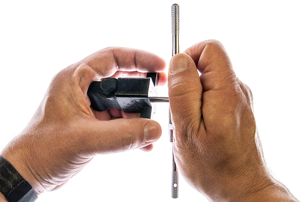
Two threads need to be tapped in each opening of the interfaces. If it is hard to keep the tap aligned with the hole direction, you can print some helping tools that will guide the tap. There are 4 of them, for the tank interface and for vessel interfaces, for each of two threads on them. If you print with PLA, avoid cutting threads too fast, it is really easy to overheat the plastic with the friction alone and ruin the thread, one half-turn every 2 seconds is about the optimal speed.
To ensure that bumpy 3d-printed surface does not lead to leaks, chamfer all of the threaded holes with chamfer drill or conical abrasive stone, so that the rubber ring is pressed against smooth inclined surface.
Fine parts
- hollow screw
- hose adapter
- hose sleeve
Fine parts need to be printed with 0.4mm nozzle and 0.1mm layer height.
The trickiest part is the hollow screw, as it is relatively highly loaded for its thickness and because of its preferable print orientation. To make sure it's strong enough you may try several strategies:
- print it sideways (supports needed and it may be tricky to cut thread on them afterwards)
- to keep layers thin, speed low and temperature high, without cooling (this make sure that layers are squished together and have enough time and temperature to fuse)
- remelt in powder salt (tricky to fine tune the temperature and time, but may be worth it)
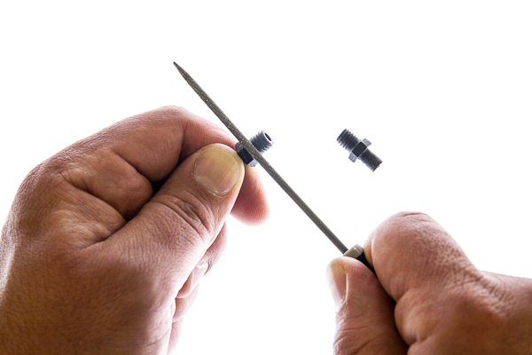
However I recommend buying M8 plastic (nylon) screws, drilling 4mm holes in them and shortening their heads, that may be way easier. Such modified nylon screws is what you can see on the illustrations of the build instructions.
For the hollow screw and adapter: after printing, drill the inner hole to 4mm and thread the cylindrical part with an M8 die. If you struggle with threading there are two helping tools for holding a die and keeping the screw straight.
File the end of the thread of the adapter where the rubber ring goes with a round file, that decreases the chances of water leaks. As for the hose sleeve, there are some thin walls on top, usually they are not a problem if you print several at once, but if you are having troubles printing only one, set some minimal layer time and try using more cooling for this part.
Frame: T-mounts, X-mounts, and small brackets
They are heavily loaded, but their dimensions do not need to be precise. You can print the parts with 0.8mm nozzle, 0.5mm layer height and up to 100% infill. Thin single layer sacrificial walls are here on purpose, the complicated holes are printed better without the need of supports. Drill them or just push through with the screw. Heat up the nuts before pressing them inside hexagonal holes to avoid cracking.
Optional tools: Tapping tool, threading tool, wrench
Those are not really necessary, especially if you already have experience and tooling for tapping and threading, but I made them because during developing and prototyping I had to do a lot of threading and tapping of those particular parts and doing it free-hand introduced significant amount of crooked threads. After printing drill the holes in tapping tools so the tap can move along but without significant slack. For the die-holding tool attach a long m4 screw which will rest inside a die, it helps guiding the work so that the thread is coaxial with the inner tube.
Enclosure
Front and back
0.8mm nozzle, 0.5mm layer height, infill doesn't matter, since the parts are thin. You may want to use M3 thread inserts for the screen mount or screw directly. You may have to file the rectangular window to fit the screen inside. The holes do not cause the need in supports. Drill the channels for buttons so their inner surfaces are smooth.
Buttons
They are easier printed in bulk with print cooling on max. That way you don't need to worry that each layer has enough time to cool before the next layer is printed. Print with smaller layer height about 0.2mm to increase layer bonding and the strength of the parts will be sufficient. Sand or file the sides so they don't get stuck inside the channels of the enclosure.
Agitation
0.8mm nozzle, 0.3mm layer height is recommended, other diameters will do fine, just don't exceed layer height of half of nozzle diameter, those parts need strength in the weakest direction for 3d-printing.
Cap
You may have to experiment and tweak the parameters of the model depending on the filament and the printer. In case you really don't want to touch any of the parametric models, sometimes you can manage small changes in part size just with scaling and small changes in wall thickness just with layer expansion in your slicer. Otherwise, refer to modifying parts to learn using parametric model for generating the perfect STL.
The cap should hold on to the tank by itself and not rotate when the torque of at least 0.25 N·m is applied, but not too tight so you can put it on and off without struggling and overloading the force gauge, to which the tank is mounted. Since the flaps of this part are loaded in the worst way possible you may have to change the parameters anyway to balance between their strength and resilience. Print with lower layer thickness to reduce probability of breaking it between layers.
Agitating rod
It is important to get the size of the servo mounting hole correct. The spline on the servo shaft needs to cut grooves inside the rod during first mounting and hold there tightly during operations. If the hole is too small, you can't put the shaft at all, if it is too big, the rod will rotate freely. In order to find an optimal hole size you may want to print the servo gauge with several hole sizes to find the optimum. Print the gauge with exactly same settings as you plan to use on the rod itself. If you really don't want to touch any of the parametric models, you may play with layer expansion setting in your slicer or heat up the shaft a little in case the hole is too small, so it melts into the rod easier, or use some glue if the hole is too big. Otherwise, read the modifying parts, there is a detailed description of using parametric model to generate the perfect STL for your part.
Waterproofing the force gauge
If you intend to use the machine with heated water bath, the force gauge should be water-tight. There is a relatively easy way of waterproofing the force gauge using silicone sealant and silicone tubing.
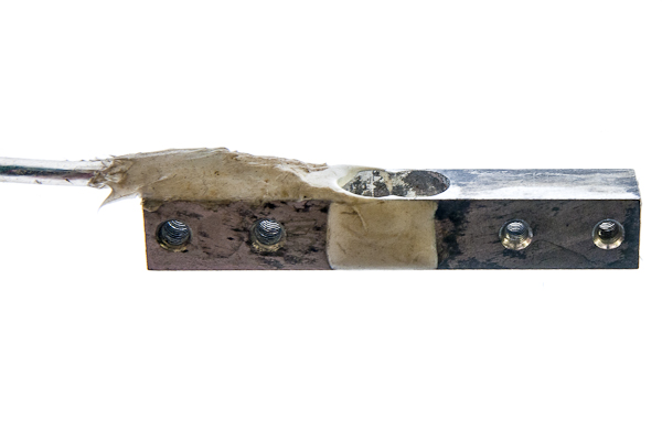
Put the four wires of the force gauge into thin silicone hose (ID about 2mm), apply some amount of sealant directly to the wires where they meet the gauge, about 30mm is enough, so that the wires adhere to the hose when you slide it all the way towards the force gauge. Apply sealant on top of the tube, closing any exposed parts of the gauge completely and everything together. Let it dry for a day after you are done.