OpenAutoLab
Free and open-source automatic film development machine.
OpenAutoLab is an attempt at making a cheap and simple film developing machine. Inspired by Jobo Autolab, but cheaper, more repairable and open source. Agitation is done by periodically moving fully submerged film, not rotating the drum constantly, so it is also more flexible, as it supports black-and-white processes.
- Parts contains information about all used electronic and mechanical components.
- Build Instructions explains how to build the machine from scratch.
- Main Board concentrates on main board schematics and PCB layouts.
- Arduino Code contains build instructions for the source code of the controller of the machine.
- Usage Instructions explains how to use the finished machine.
- Web Updater allows firmware upgrades on the main board.
This site is automatically generated from OpenAutoLab Github repository.
This is still work in progress, so some information may be missing or unclear. Feel free to ask questions via email mailto:openautolab@kauzerei.de
This site contains detailed instructions for building OpenAutoLab.
- Start out by aquiring all parts of the machine.
- If you already have all parts, refer to building.
- If you want to 3d-print some or all of the parts yourself, refer to making parts.
- If some parts like magnets, valves, hoses, pumps, vessels differ from the ones on the parts list in such a way, that you need changes in models for 3d-printing, refer to modifying parts.
- If you want to modify the main board, refer to the
main_boardchapter.
Parts to build OpenAutoLab
Components to buy
Main board
- Arduino Nano
- Pololu DRV8874 or similar
- LM2575-5.0BT or similar (LM2576-5.0)
- 330uH 1A coil
- 100uF 16V capacitor
- 330uF 25V capacitor
- 2x SB140, or any other Schottky diodes, that survive short 2A burst from the motor
- 8x Phoenix PT 1,5/ 2-3.5 1x2 or similar P3.8 screw terminal blocks
- 4x Phoenix MKDS 3/ 2-5.08 1x2 or similar P5.08 screw terminal blocks
- 3x 6x6mm push switches
- 2x ULN2064 or similar darlington transistor arrays (ULN2065, TD62064APG)
- 2x SPDT ON-ON (or SPST) toggle switch, for example APEM 5026
- 3x1 right-angle pin header for connecting servo (or bend straight ones)
- 2x1 pin header for connecting fresh water pump switch
- 2x1 pin header for connecting main power switch
- 4x1 socket header for connecting the scale
- 4x1 socket header wire for connecting display
If the parts listed are unavailable, feel free to modify the PCB to fit the components you want to use instead.
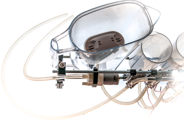
Electromechanics
-
6x normally-closed 12V valves. They are somewhat tricky to buy, as they have no proper name. Try including "6.2mm" which is outer diameter of connecting piece into your search query. See the picture as a reference, try to find the valves that look the same. Number of valves depends on what process you want to run. 1 valve for water, 1 valve for waste, plus 1 valve for each chemical. 8 is the maximum number supported by the current board
-
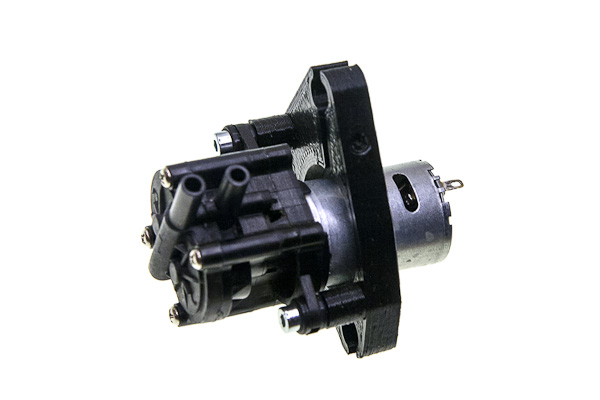
ZC-A210 or similar 12V gear pump, capable of running in two directions at a speed of about 2l/min for prolonged times
-
Weight cell and HX711 ADC for it
-
MG90 servo
-
Brita filter for water
-
Any pump that can work for prolonged periods without overheating. See picture for reference, no part name just like with valves
-
Float switch
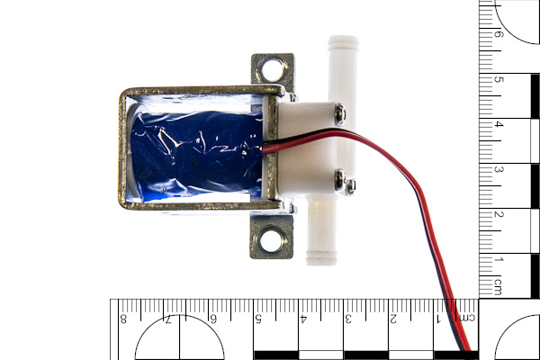
Solenoid valve
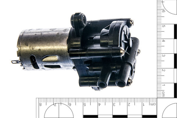
Bidirectional gear pump
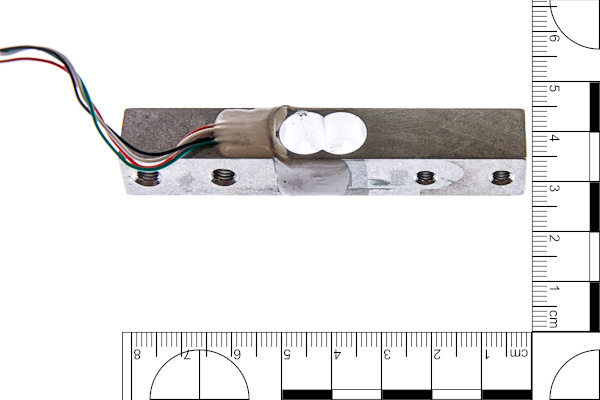
Weight cell
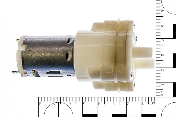
Membrane pump (clean water pump)
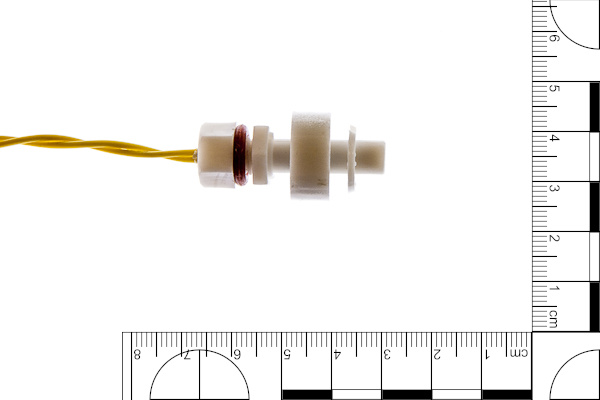
Float swich
Other parts to buy
- M8 threaded rod and nuts.
- Flexible silicone hose. 6mm ID 9mm OD is recommended.
- Silicon rubber rings. I suggest 8mm ID, same as thread diameter (mentioned later).
- 5x T-pipes, one for each valve minus one.
- Developing tank. AP developing tank is recommended.
- 4x Vessels for chemicals. I suggest STANDARDMÅTT from IKEA.
- 12x3mm cylindrical neodymium magnets.
- Borrow or buy M8 tap, a tap holder and M8 die for cutting threads. I wouldn't even try to make 3d-printed water-tight hose connections, tapping and threading are better be done by hand.
- 6x M8x8 plastic screws and 4mm drill as a more practical alternative to 3d-printed screws. More on that in lower_rail section.
- Sous Vide and a water-tight container for heating the vessels with water.
Parts to 3d-print
STL files for all mentioned parts can be generated using the parts/generate_stls.sh script in the repository.
They are also built automatically using GitHub Actions and uploaded as GitHub releases.
Find the latest openautolab-stl.zip here.
Stl-files are divided into several groups: agitation, enclosure, frame, lower_rail, and upper_rail.
Those groups correspond to modules which are described in different chapters.
Filenames follow 'group_part.stl' naming, where 'part' is the name used in building instructions often dropping the 'group' part.
Frame
The machine consists of an L-shaped frame, which holds two rails: the lower rail where the vessels and tank are mounted, and the upper rail, where the pumps, valves and electronics are mounted. 3d-printable parts are generated from frame.scad and can be customized to use different threaded rod diameter.
- 16x x-mount. Each pair of parts holds two rods together, two rods are mounted on each of two sides of each of two rails, therefore 16 parts in total.
- 4x t-mount. Each pair holds two rods at a right angle, the frame needs 2 such L-shaped structures to hold the rails.
- 4x small_bracket for mounting electronic enclosure on the upper rail.
Lower rail: vessel and tank interfaces and mounts
To connect the vessels and the developing tank to valves and the pump magnetic hose interfaces are used. To attach those interfaces to the lower rail magnetic holders are used. The interface for the tank has also a light-trap that prevents fogging the film through the hole, to which the hose is connected. Magnetic holder for the tank is mounted to the weight gauge for measuring the amount of fluid in it. All of those parts are generated from lower_rail.scad and can be customized to fit magnets of different size and force.
- 6x hollow_screw - to mount hose interface to vessels and tank through a hole.
- 5x interface - the interfaces for the vessels.
- interface_light_trap - larger interface with light trap for the developing tank.
- 6x interface_cover - mounts magnet to the interface.
- 6x hose_adapter and
- 6x hose_sleeve - to make hose fittings.
- 5x magnetic_holder - to attach vessels to the rail.
- magnetic_holder_wg - to attach developing tank to the weight gauge.
- 6x magnetic_holder_cover - to mount magnet to the holder.
- 2x weight_gauge_bracket - to mount weight gauge to the rail.
- 2x filter_support - too keep heavy filter from breaking the hollow screw.
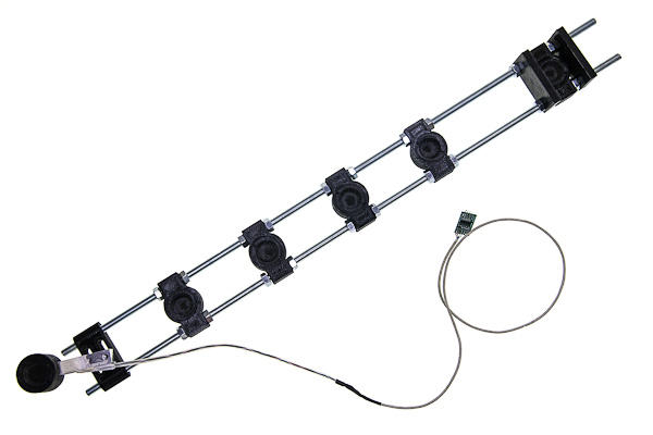
Upper rail: mounts for valves, pumps and electronic box
The parts that do not have to be submerged into water when developing in heated bath are mounted on the upper rail. Main bidirectional pump, auxiliary pump for clean water, magnetic valves, enclosure with electronics, and optional battery holder are mounted with respective brackets tightened by M4 screws and nuts. Main pump and valves are connected together with silicon hose and T-pieces.
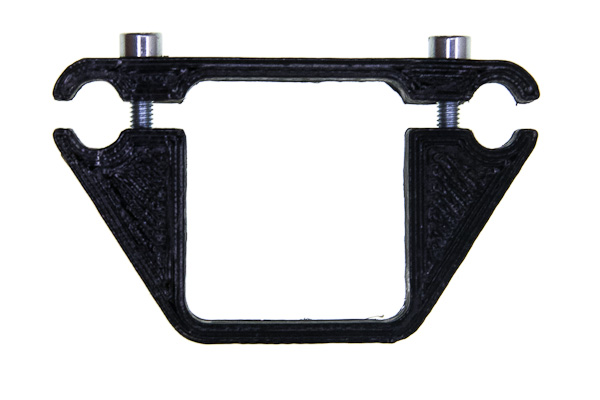
- 12x valve_bracket - each valve is supported by a pair of brackets.
- main_pump_bracket - consists of two parts in one stl to mount the main pump.
- filter_pump_type*_bracket - two parts in one stl to mount the filter pump, two kinds of pumps supported.
- 2x filter_attachment - to hold float sensor and input hose on the filtered.
Agitation
To agitate the chemicals inside the developing tank servo-powered rod should be attached to the top of the tank. Parts compatible with AP developing tank are provided. Parts compatible with other tanks should be designed individually for each one.
- agitation_rod - goes into developing tank just like the rod for manual agitation.
- agitation_cap - goes on top of the tank, holds the servo with the rod attached.
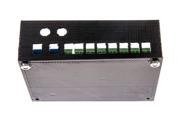
Enclosure
Main board is hidden in the enclosure, which is mounted onth the upper rail
- front - front side of the enclosure, here the screen is mounted and the buttons are put through.
- back - rear side of the enclosure, here the board and the switches are mounted.
- buttons - plastic rods, that push the switches on the board.
Optional tools
It can be hard to cut good threads in small hard plastic parts, to simplify this process, there are tapping and threading helping tools in the optinal folder. Four different tapping tools are there to keep the tap perpendicular to each of the four surfaces, where the threads need to be. Tapping tool holds the die coaxial to the hollow parts that need to be threaded. Wrench has two sides for holding hollow screws and hose adapters during threading. Nut spinner is small round wrench which makes it easier to put nuts on long threads. Servo gauge is a set of test holes to find out which one fits best to your servo.
Power supply
The machine is intended to use 12V power supply, since the rated voltage of pumps and valves is 12v. The internal DC-DC converter can take up to 40V. It's better to provide stable 12V input. That being said, I've used 4 cells of 18650 type without voltage stabilisation, which can give more than 16V fully charged, multiple times and the hardware is fine. The battery holder and battery enclosure to be bounted on the upper rail are kept as hidden features for now, available directly from .scad files. But use them on your own risk or stabilize the battery output before the machine.
Building OpenAutoLab
This is a detailed description of building OpenAutoLab.
If you are using a plant container for heated water bath, note that you may have to move around some of the components a little, since different containers may have inner structures you need to avoid, see section about lower rail. If you have any pre-built modules like main board or one of the rails, just skip the section.
If you are 3d-printing the parts yourself, please refer to making parts, it contains useful information about the print settings and post-processing.
If you want to change the measurements of some parts, due to differently sized magnets, hoses, threaded rods or other components, refer to modifying parts, it describes how to modify parametric models of all 3d-printable parts to meet your needs.
Building frame
By the end of this chapter you will have the skeleton of the machine with most components mounted on the frame.
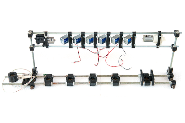
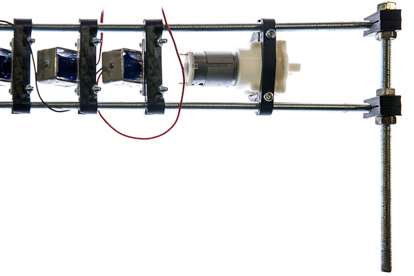
Building upper rail: valves, pumps and mount for electronic box
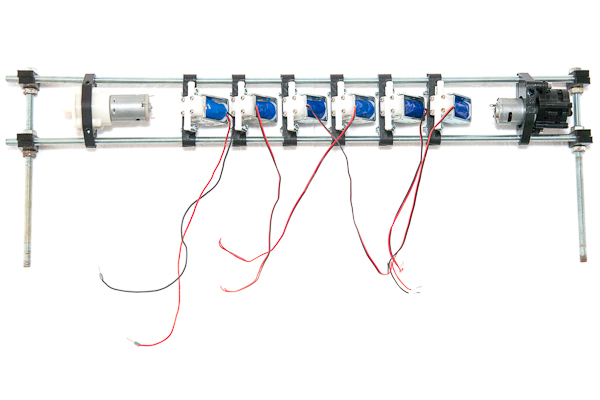
By the end of this section you will have non-water-tight top part of the machine. It is possible that you will have to change placement of some parts due to individual differences in size of components sourced from different manufacturers. The difference should not be drastic, so the mentioned measurements are a good reference.
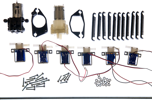
Parts list
| No | Part | Quantity | Filename if 3d-printable |
|---|---|---|---|
| 1 | Main pump | 1 | |
| 2 | Two-part bracket for the main pump | 1 | upper_rail_main_pump_bracket.stl |
| 3 | Fresh water pump | 1 | |
| 4 | Two-part bracket for the fresh water pump | 1 | upper_rail_filter_pump_type1_bracket.stl or type2 |
| 5 | magnetic valves | 6 | |
| 6 | brackets for the valves | 12 | upper_rail_valve_bracket.stl |
| 7 | M4x15 screws | 2 | |
| 8 | M4x20 screws | 12 | |
| 9 | M4x25+ screws | 3 | |
| 10 | M4 nuts | 17 | |
| 11 | M8 threaded rods of length 600mm | 2 |
When building the rail together, do not tighten the screws all the way, keep the assembly somewhat flexible, as you may want to move the brackets around before fixing them in place.
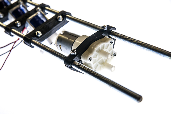
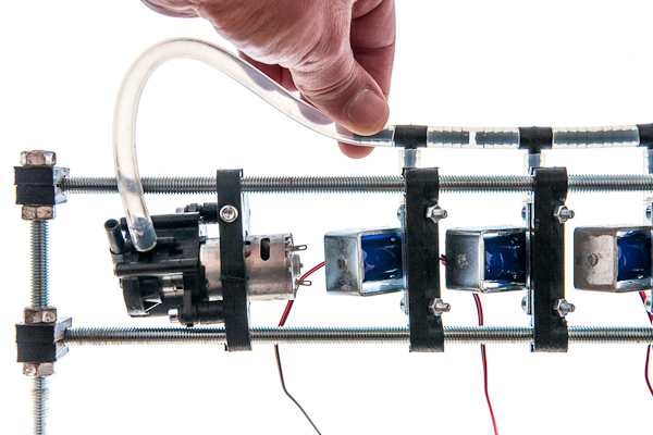
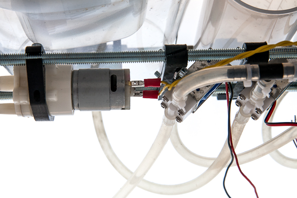
Take the main pump and mount it on its bracket with two M4x15 screws.
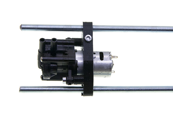
Push the threaded rods through the mount and tighten the M4x25 screw (or longer) fixing the position of the pump about 20mm away from the leftmost end of the rod. Note that connecting pipes should point upwards from the pump. It starts better when the gears inside of it are immersed into a small amount of remaining liquid, rather then when the gravity completely pulls the liquid out.
Take one of the valves and fix it about 2cm away from the pump leaving some space for the electrical connections. Use M4x20 screws and nuts. Mind the orientation at which the valves are mounted: the connecting tube that protrudes more should face downwards. The reason os that they are better holding pressure in one direction and shold be connected to withstand higher pressure generated by pump pushing liquids towards the valves. The pump sucking through them in the other direction cannot create pressure difference greater than atmospheric and the valve does't need to be as strong this way.
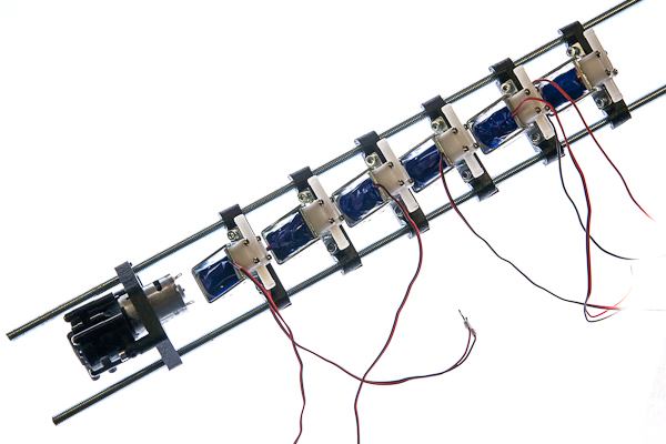
Mount the rest of the valves onto the rail a couple millimeters apart from one another.
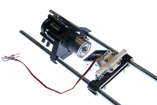
Take the fresh water pump brackets and screw them together with two M4x25 screws (or longer) leaving 3mm gap.
Place the pump between the brackets, and mount them onto the rail, about 20mm away from the rightmost valve. When you are sure that all parts fit nicely, tighten all the screws.
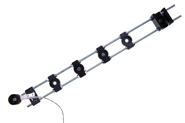
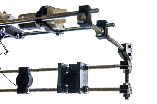
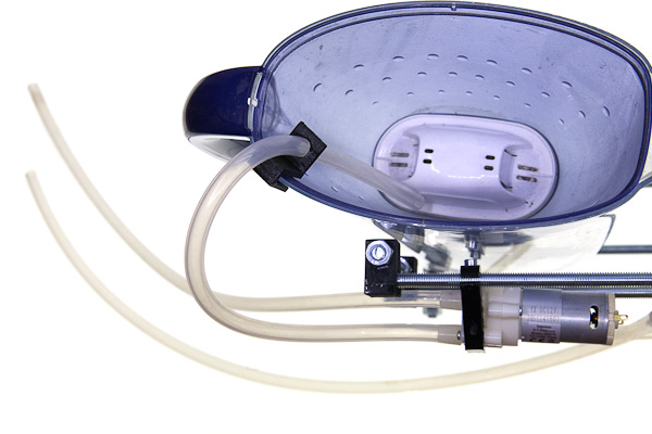
Building lower rail: vessel and tank interfaces and mounts
By the end of this section you will have a water-tight bottom part of the machine. It is possible that you will have to change placement of some parts due to differences in placement of the structures inside the outer box.
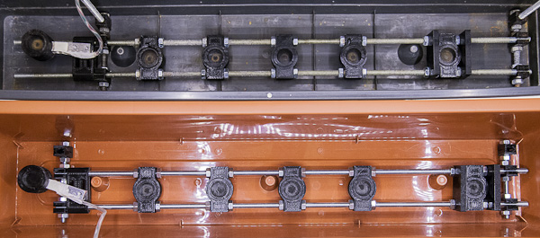
The difference should not be drastic, the picture is a good reference anyway. If the force gauge was not originally waterproof, follow the instructions in making parts to make it waterproof first.
Parts list
| No | Part | Quantity | Filename if 3d-printable |
|---|---|---|---|
| 1 | rod-mountable magnetic holders | 5 | lower_rail_magnetic_holder.stl |
| 2 | bar-mountable magnetic holder | 1 | lower_rail_magnetic_holder_wg.stl |
| 3 | force-gauge mounting brackets | 2 | lower_rail_weight_gauge_bracket.stl |
| 4 | larger magnet covers with outer thread | 6 | lower_rail_magnetic_holder_cover.stl |
| 5 | filter supports | 2 | lower_rail_filter_support.stl |
| 6 | magnets | 6 | |
| 7 | Waterproof force gauge | 1 | |
| 8 | threaded rods M8 of length 600mm | 2 | |
| 9 | M8 nuts | 24 | |
| 10 | M6x25 screws | 2 | |
| 11 | M4x12 screws | 2 |
Take two threaded rods and place one nut on each of them about 135mm from the end. Push them through one magnetic holder and fix with two nuts on the other side.
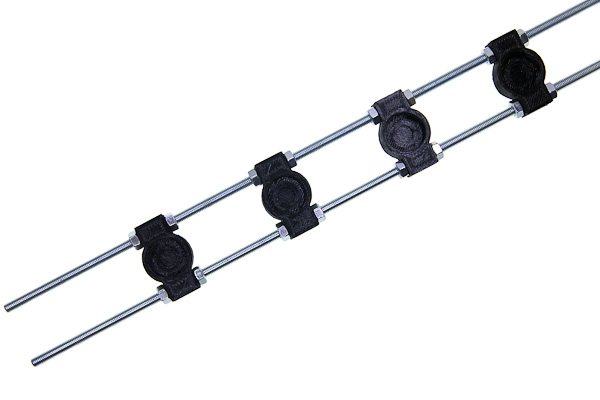
Place two more nuts about 65mm to the right from the previous two. Repeat nuts-holder-nuts-space pattern for a total of 4 holders.
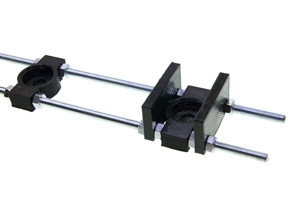
The rightmost holder is for the filter and should be further away due to filter size and requires two additional supports due to its weight and instability. So, after the fourth holder keep about 150mm of space, then place parts in following order: nuts, support, nuts, holder, nuts, support, nuts. The idea is that each part is fixed on both sides and is in the contact with 4 nuts in total.
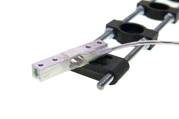
Take the force gauge, and the pair of mounting brackets and fix the gauge on the left about 20mm from the very end of the rods by threading each screw through two brackets into the gauge. Mind the orientation of the gauge, the arrow must be on the free side and should point downwards, and the angle must be fine tuned later so that the tank is as far from touching any of the walls as possible.
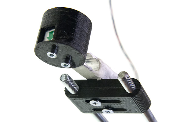
Mount the last holder to the other side of the gauge with two M5 screws.
Place the magnets in the same orientation (all north pole up or all north pole down) in each of the six magnetic holders.
Screw a larger magnet cover with outer thread into each of the six magnetic holders.
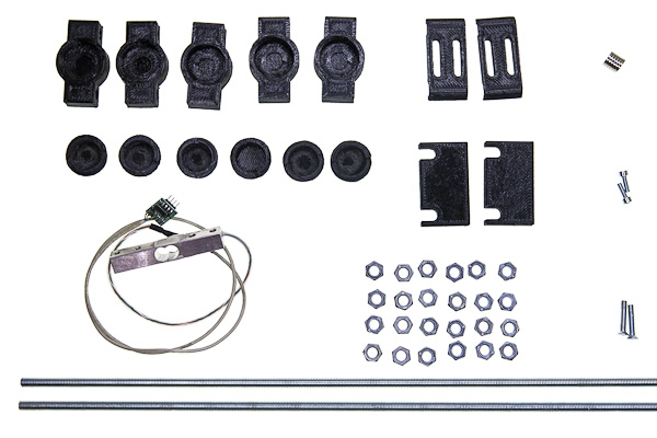
Bringing two rails together
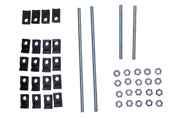
Parts list
| No | Part | Quantity | Filename if 3d-printable |
|---|---|---|---|
| 1 | T-mounts | 4 | frame_t-mount.stl |
| 2 | X-mounts | 16 | frame_x-mount.stl |
| 3 | M8x210mm threaded rods | 2 | |
| 4 | M8x110mm threaded rods | 2 | |
| 5 | M8 nuts | 20 | |
| 6 | M4x20 screws | 4 | |
| 7 | M4 nuts | 4 |
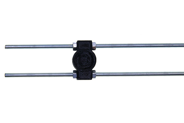
You need to have two pairs of X-mounts on each of four rods to hold one rail on one side. Each pair should be able to be pressed together by two nuts in order to tightly hold the threaded rod of the rail.
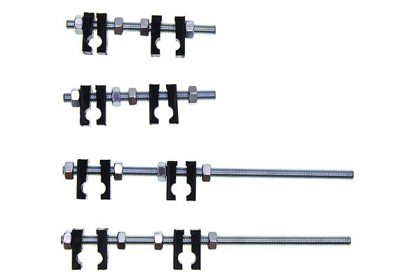
To achieve said structure, loosely put the parts in the following order on each of four rods: nut, two X-mounts (two round cutouts facing each other), two nuts some distance apart, two more X-mounts (also cutouts together), nut.
Take the upper rail and two longer (210mm long) rods.
Place both ends of the rail (left and right) between pairs of X-mounts and tighten the nuts. Make sure that perpendicular rods are in front of the rail, not on the rear side.
Repeat the same procedure with the lower rail and shorter (110mm) rods. Note that exact placement of those perpendicular rods is not really important, the distances between them should be the same for the lower and the upper rail. The left one could be mounted to the right or to the left of the weight gauge bracket, depending on available space in the outer container, you may have to experiment.
Now use 4 T-mounts to fix the rails together: put the mounts loosely on the ends of the rods of the lower rail.
The perpendicular rods of the upper rail are inserted between those pairs, which are then pressed against each other with screws.
Building agitation module
Parts listed
| No | Part | Quantity | Filename if 3d-printable |
|---|---|---|---|
| 1 | Tank cap | 1 | agitation_rod.stl |
| 2 | Agitating rod | 1 | agitation_cap.stl |
| 3 | MG90 servo | 1 |
If you have some special developing tank and need to make parts that fit it, or 3d-printing them for the recommended AP developing tank, refer to modifying parts, it has description of how to make the right rod and cap. In this document it is supposed that you already have the parts that fit your tank perfectly.
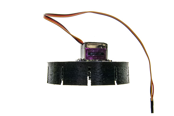
Mount the servo on tank cap in such a way, that its axis is in the center of the cap using the screws provided with the servo.
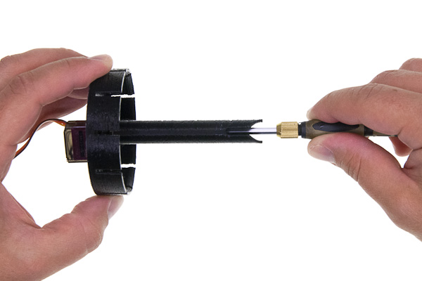
Take a long screwdriver and fix the mixing rod to the servo with the M2.5 screw also provided with the servo.
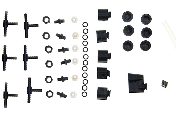
Connecting hoses
Parts list
| No | Part | Quantity | Filename if 3d-printable |
|---|---|---|---|
| 1 | Silicone hose 6mm ID, 9mm OD | ||
| 2 | T-connectors for 6mm hose | 5 | |
| 3 | hose sleeve | 6 | lower_rail_hose_sleeve.stlv |
| 4 | hose adapter | 6 | lower_rail_hose_adapter.stl |
| 5 | hollow screw | 6 | lower_rail_hollow_screw.stl |
| 6 | silicone rings | 12 | |
| 7 | straight vessel interfaces | 5 | lower_rail_interface.stl |
| 8 | Tank interface with a light-trap | 1 | lower_rail_interface_light_trap.stl |
| 9 | interface magnet cover | 6 | lower_rail_interface_cover.stl |
| 10 | Filter attachments holder | 2 | upper_rail_filter_attachment.stl |
| 11 | magnets | 6 | |
| 12 | cable ties |
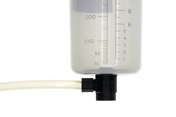
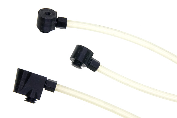
The vessels and the developing tank are connected to the hoses with interfaces, which are fancy L-shaped tubes with inner M8 threads on each end and a magnet on the bottom. The top thread is for the hollow screw, that is put through the hole in the bottom of the vessel, a gasket ring and then tightened to the interface itself.
The side thread is for the hose adapter. This part is designed to be interchangeable, because of how easily it could be accidentally broken. For the same reason it is designed with redundant sleeve that holds the hose and adds to the strength of the part.
Mounting hose adapters
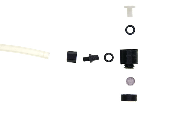
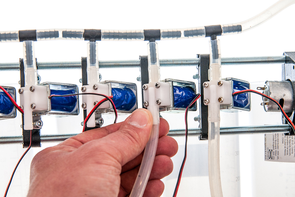
Cut 6 hoses for vessels, filter and tank. Their lengths need to be enough to connect the upper rail and the lower rail and to allow comfortable handling of vessels, mounted to them. Recommended length is about 300mm. Now connect each hose to adapter as follows.
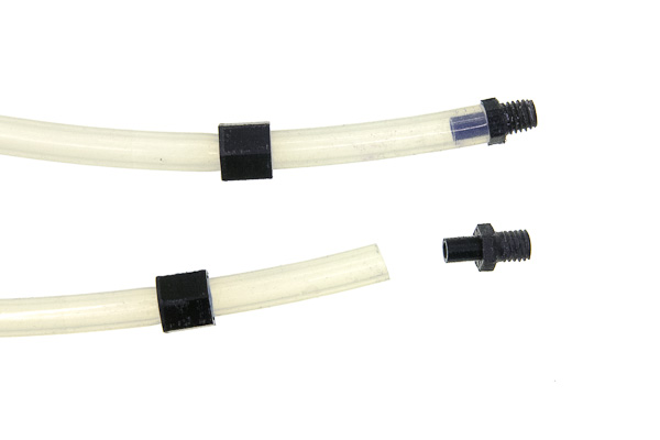
First, the sleeve is put on the hose, the side with hexagonal cutout facing the end of the hose. Then the narrow side of the adapter is put over the hose.
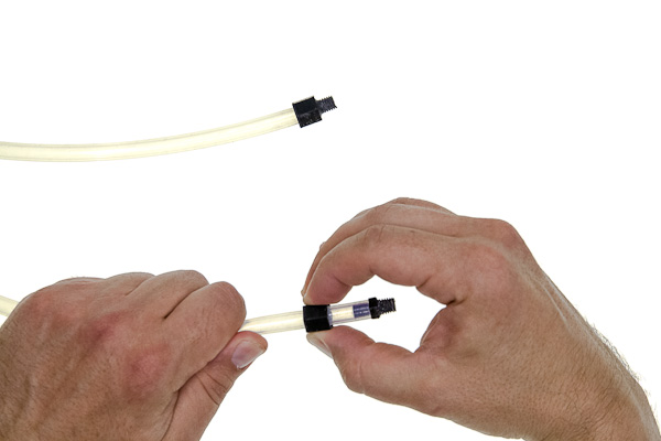
Then holding the hose with one hand, slide the sleeve with the second hand. The pulling force will stretch the hose so it becomes narrower and it is easier to fit the sleeve on top of it, however it should be done carefully not to pull the hose away from the assembled adapter.
Screw those adapters on the sides of the interfaces (not on top part which is opposite to the magnet). You can use TPFE tape, silicone or rubber ring (recommended) to make threaded connection water-tight. Keep in mind, that in case adapter is broken, you need to be able to unscrew the thread.
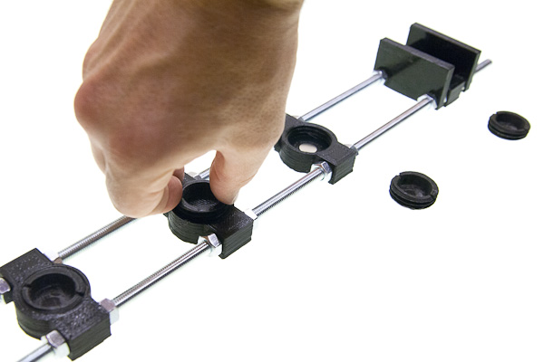
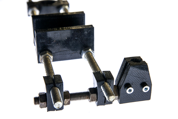
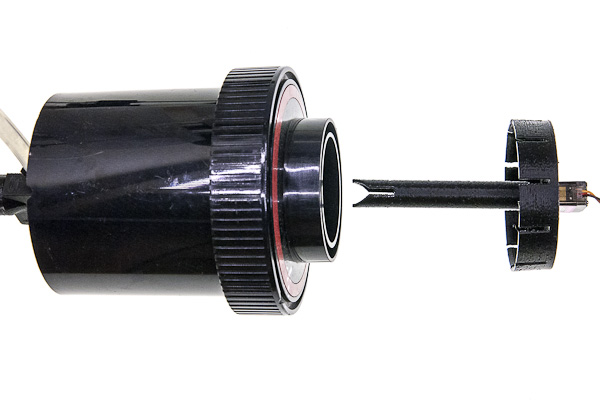
Preparing vessels and tank
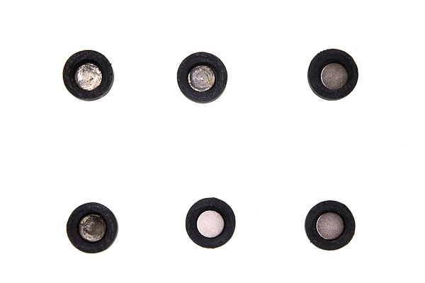
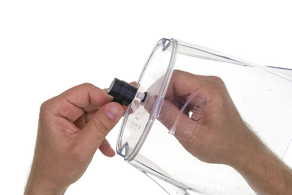
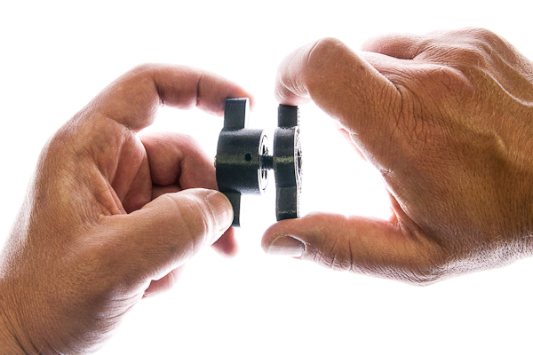
Put 6 magnets into the smaller magnetic covers in the same orientation you put them into magnetic holders.
![process of screwing cap on one interface, near lie assembled and disassembled]
Screw those caps onto interfaces.
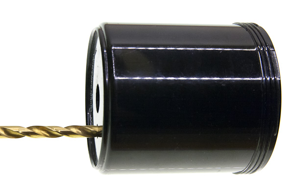
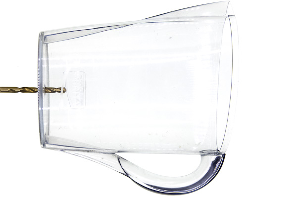
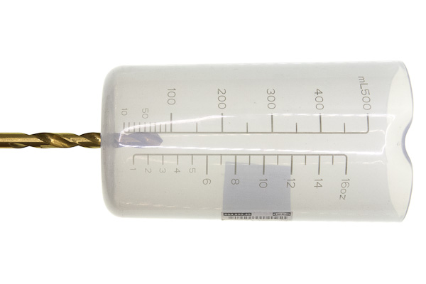
The machine is designed with AP developing tank, Ikea 500mL shakers and Brita water filter in mind. If you are building the machine from scratch you need to drill 8mm holes in each of those items: 17mm offset from center for the tank and dead center for the others.
Then for each one of those repeat the following mounting process.
Put the hollow screw through the hole from the inner side, such that the thread is sticking outside. Put a silicone gasket on the thread. Screw the interface on, magnetic side down. Do not over-tight, especially if you have a 3d-printed screw. Tighten just that the interface is not unscrewing itself when forces are applied by the dangling hose during normal operation.
Finishing the liquid connections
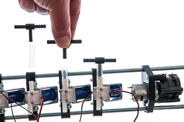
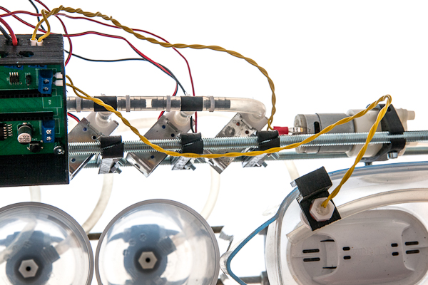
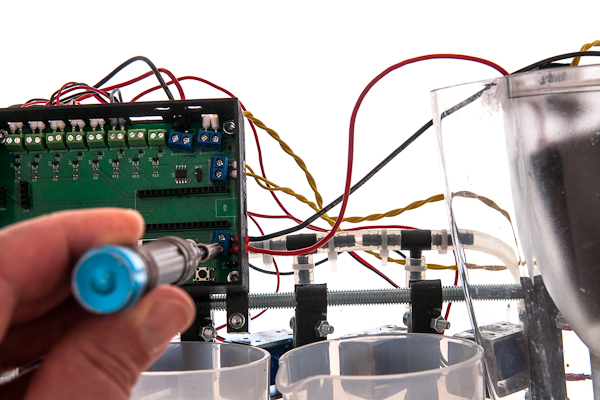
Cut 5 pieces of hose, each of which is just long enough to connect a T-piece with a valve and put T-pieces on top of the five leftmost (nearest to the main pump) valves. Note that the picture is taken from the back side of the machine.
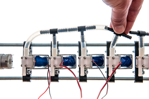
Cut one more slightly longer hose to connect the last valve to the side of the T-piece of the neighbouring one. From now on measure the length of the hose to be cut judging from the distance of components that it connects. Cut four more short hoses and connect 5 T-pieces together. Note that the picture is taken from the back side of the machine.
Connect the main pump to the only T-piece left.
Connect the other side of the pump to the tank.
Connect the four hoses attached to two vessels, water filter to valves 1 through 6, the sixth valve is for dirty water output, it needs to be slightly longer, because it leads outside of the machine to your waste water container.
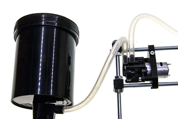
Cut the hose for clean water input about the same size as the waste water hose, it should reach the source of clean water outside the machine. Connect it to the input of the filter pump. Input connecting pipe is typically the one further from the axis of the pump.
Cut about 300mm long hose for the filter input. Connect it to the output of the filter pump and fix its other side to the input of the filter. Output connecting pipe is typically the one closer the axis of the pump.
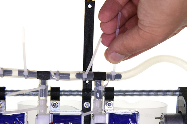
Secure each end of each hose with a cable ties.
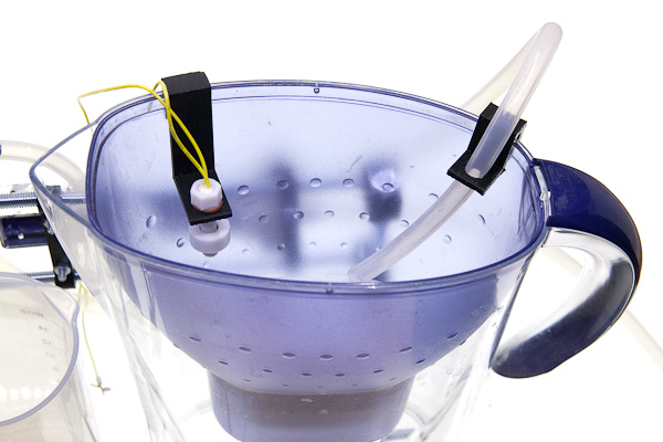
Put the level sensor on the filter input so the filter never overflows.
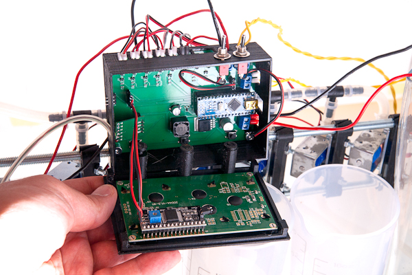
Mounting and connecting electronics
If you want to make the PCB yourself, or just to understand its work better better, refer to main_board subdirectory of the repository. It contains schematics and board layout in KiCAD format, along with some insights about its production. In this document it is supposed that you already have a PCB with all components soldered to it.
Mounting PCB
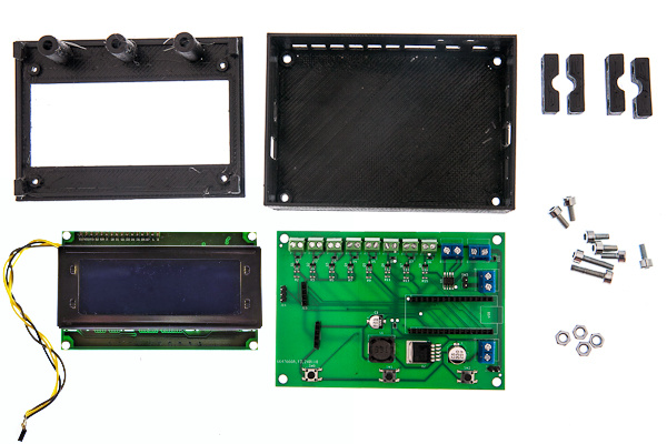
Parts list
| No | Part | Quantity | Filename if 3d-printable |
|---|---|---|---|
| 1 | PCB | 1 | |
| 2 | 20x04 LCD display with i2c interface | 1 | |
| 3 | Front half of the electronic enclosure | 1 | enclosure_front.stl |
| 4 | Back half of the electronic enclosure | 1 | enclosure_back.stl |
| 5 | plastic buttons | 3 | enclosure_buttons.stl |
| 6 | double brackets for mounting enclosure | 2 | frame_small_bracket.stl |
| 7 | M4x20 screws | 4 | |
| 8 | M4x10 screws | 6 | |
| 9 | M4 nuts | 6 |
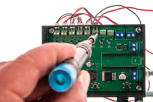
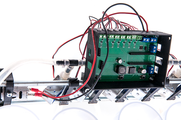
Place the board inside the back half of the enclosure. Put two M4x10 screws through the upper holes in the board and tighten them with nuts.
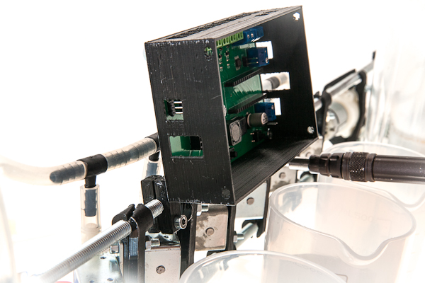
Put two M4x20 into the lower holes and drive each one through each bracket to fix the ecclosure to the upper rail. Tighten the brackets with one more M4x20 screw each, see picture for reference.
Connecting power electronics
Before valves can be connected to the main board, the wires need to be prepared.
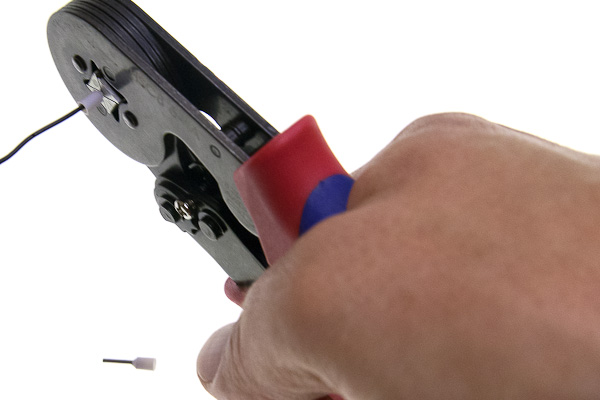
The optimal way is crimping the ferrules. Covering ends of wires with solder using soldering iron is not optimal, since the solder slowly deforms under pressure with time and connection may become loose, but better than nothing. Screwing the wires as is is strongly not recommended.
If the pumps have already pre-soldered wires, you can use them or replace if the length is not enough. A nice way is to solder nothing to the pumps and use the contact terminals instead.
Put each pair of wires of each valve into the screw terminals and tighten them with screws. Polarity does not matter in case of valves.
The second terminal block from the right is the main pump. Polarity is important here, but your pump may theoretically have different polarity. In case it does, don't worry, just do the test run in the end and check that the pump moves the water in the right direction and change the polarity of this pump if needed or reverse the hoses connections.
The rightmost terminal block is for the clean water filter pump. The upper one on the right side is for the magnetic sensor for the filter. Both cave no incorrect polarity, unless you are using some bidirectional pump instead of the recommended one.
Connect the lowest terminal block to the power supply, here the polarity is the most important, make sure that the negative contact is connected to the top terminal, and the positive to the lower one.
Signal-level electronics and front panel
Connect the force gauge, to 4-pin connector and the agitation module to a 3-pin connector as depicted, the polarity is very important.
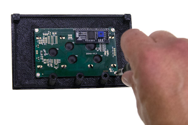
Place the top cover of the electronic box upside down and mount the screen.
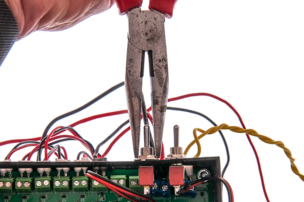
Mount the pump switch.
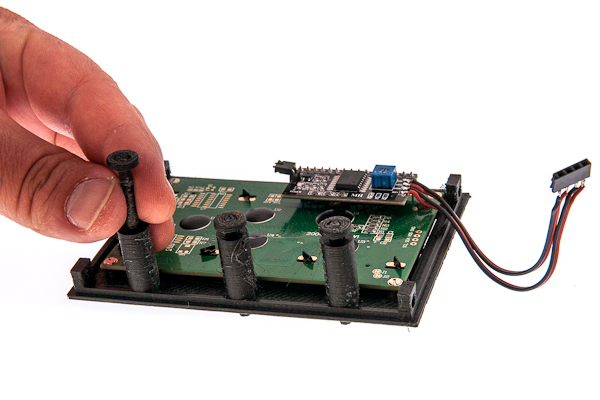
Insert three plastic buttons into their places. If you do not invert the box completely they do not fall out, but if you struggle with them, you can hold the box screen-down and invert the whole frame to put the box together.
Attach the screen and switch connectors to the board and put the box together.
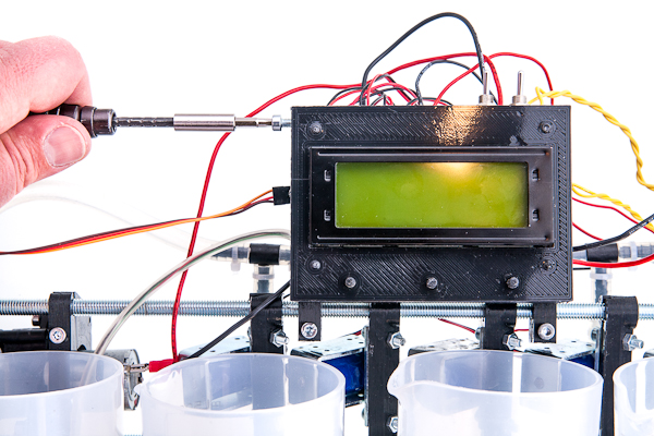
Fix the box halves together with four side-mounted M4x10 screws.
Making parts
This is a detailed description of making parts for the OpenAutoLab yourself. It contains useful information about 3d-printing and post-processing of the printed parts as well as making force-gauge water-tight for submerging.
Most of the plastic parts can be 3d-printed with any filament, such as ABS, PLA or PETG. All of those filaments absorb water to some degree, so have in mind, that they may fail at some moment.
- ABS seems to be fine after 2 years of testing in real conditions, which means some residue water and chemicals was always inside the machine.
- PLA seems to degrade more on heavily loaded parts that are submerged in water: the ones that hold the rods together. I had cracks in interfaces too, but much more rarely. Thin walls of interface covers often suffer too, but probably that's the issue with the quality of the first layers
- No data on PETG yet.
- No data on resin prints. Probably not hard enough and potentially too transparent.
This part will be updated as the time goes.
As an owner of a cheap 3d-printer, that is incapable of high print speeds, I often recommend to increase nozzle size and layer height for some parts as a way of printing them faster. If you have only one nozzle or don't need to decrease the time of printing, you can of course print everything with one.
If you are not sure if the dimensions of some components like valves and pumps are the same with the ones that were used to design the parts and you don't feel like editing the models, you may print all of the mounting parts with 100% infill and then cut, drill and file the parts if necessary, I did that a lot while prototyping. In that case, make sure your printer does not overextrude, though. It happens when the extruder is not well calibraed or the filament is thicker than the slicer thinks.
Upper rail
All 3d-printable parts of the upper rail do not need high precision and are loaded not that heavily. I recommend 0.8mm nozzle, 0.5mm layer height, wall thickness of 2 layers and 20% infill. When using thinner nozzle, make sure wall thickness is 1.5mm or greater to withstand the load from the screws and nuts. You may heat the M4 nuts before pressing them into the parts to reduce stress and avoid delamination.
Filter attachment
You can heat up the clip a little with a lighter and bend it to the shape of the filter. I find it easier rather than modifying the model and printing until it fits ideally without modifications. Hold it about 15cm above the flame for about 10 seconds until you notice it becomes soft (you can notice that moment visually as the part becomes more glossy when PLA softens)
Lower rail
There are three types of parts in the lower rail, some are trickier to print than the others.
Bulky parts
- filter_support
- gauge_bracket
Those are similar to parts from upper rail: 0.8mm nozzle, 0.5mm layer height, (or 0.4mm nozzle and 0.3mm layer height) wall count 2 and 20% infill.
parts with 3d-printed thread
- interface, both straight and with light trap
- interface cover
- magnetic holder, both with rod and weight gauge mounting points
- magnetic holder cover
If you have calibrated layer expansion of your printer, you may want to turn it off for this print. It's better in this case to have guaranteed wall thickness and change expansion correction in the model itself. Default values are high enough that the threads move freely, even with large nozzles and layer heights; thread pitch is so large that the threads can be tightened even if the print expansion is small and there is a lot of tolerance between parts. I suggest 0.8mm nozzle and 0.2mm layer. The threads can be printed without supports, the holder with rectangular mount may need ones: so let the supports be generated for angles larger than inclination of thread walls, threshold of 70° will do.
The parts should be printed with the wall, top and bottom thickness of a couple millimeters to allow thread cutting in interfaces and keeping the part liquid-tight, and to make sure that the walls of the printed threads are strong enough.
Two threads need to be tapped in each opening of the interfaces. If it is hard to keep the tap aligned with the hole direction, you can print some helping tools that will guide the tap. There are 4 of them, for the tank interface and for vessel interfaces, for each of two threads on them. If you print with PLA, avoid cutting threads too fast, it is really easy to overheat the plastic with the friction alone and ruin the thread, one half-turn every 2 seconds is about the optimal speed.
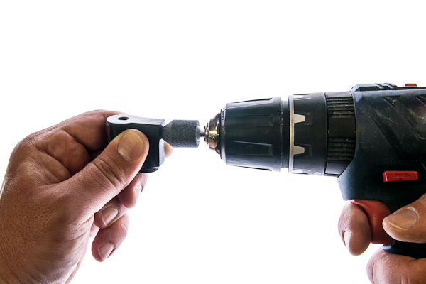
To ensure that bumpy 3d-printed surface does not lead to leaks, chamfer all of the threaded holes with chamfer drill or conical abrasive stone, so that the rubber ring is pressed against smooth inclined surface.
Fine parts
- hollow screw
- hose adapter
- hose sleeve
Fine parts need to be printed with 0.4mm nozzle and 0.1mm layer height.
The trickiest part is the hollow screw, as it is relatively highly loaded for its thickness and because of its preferable print orientation. To make sure it's strong enough you may try several strategies:
- print it sideways (supports needed and it may be tricky to cut thread on them afterwards)
- to keep layers thin, speed low and temperature high, without cooling (this make sure that layers are squished together and have enough time and temperature to fuse)
- remelt in powder salt (tricky to fine tune the temperature and time, but may be worth it)
However I recommend buying M8 plastic (nylon) screws, drilling 4mm holes in them and shortening their heads, that may be way easier. Such modified nylon screws is what you can see on the illustrations of the build instructions.
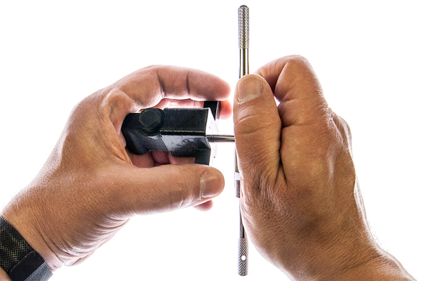
For the hollow screw and adapter: after printing, drill the inner hole to 4mm and thread the cylindrical part with an M8 die. If you struggle with threading there are two helping tools for holding a die and keeping the screw straight.
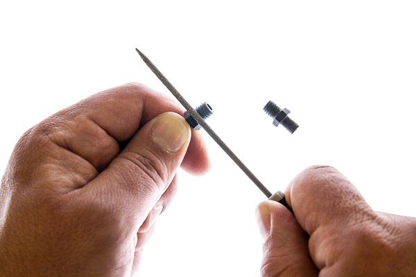
File the end of the thread of the adapter where the rubber ring goes with a round file, that decreases the chances of water leaks. As for the hose sleeve, there are some thin walls on top, usually they are not a problem if you print several at once, but if you are having troubles printing only one, set some minimal layer time and try using more cooling for this part.
Frame: T-mounts, X-mounts, and small brackets
They are heavily loaded, but their dimensions do not need to be precise. You can print the parts with 0.8mm nozzle, 0.5mm layer height and up to 100% infill. Thin single layer sacrificial walls are here on purpose, the complicated holes are printed better without the need of supports. Drill them or just push through with the screw. Heat up the nuts before pressing them inside hexagonal holes to avoid cracking.
Optional tools: Tapping tool, threading tool, wrench
Those are not really necessary, especially if you already have experience and tooling for tapping and threading, but I made them because during developing and prototyping I had to do a lot of threading and tapping of those particular parts and doing it free-hand introduced significant amount of crooked threads. After printing drill the holes in tapping tools so the tap can move along but without significant slack. For the die-holding tool attach a long m4 screw which will rest inside a die, it helps guiding the work so that the thread is coaxial with the inner tube.
Enclosure
Front and back
0.8mm nozzle, 0.5mm layer height, infill doesn't matter, since the parts are thin. You may want to use M3 thread inserts for the screen mount or screw directly. You may have to file the rectangular window to fit the screen inside. The holes do not cause the need in supports. Drill the channels for buttons so their inner surfaces are smooth.
Buttons
They are easier printed in bulk with print cooling on max. That way you don't need to worry that each layer has enough time to cool before the next layer is printed. Print with smaller layer height about 0.2mm to increase layer bonding and the strength of the parts will be sufficient. Sand or file the sides so they don't get stuck inside the channels of the enclosure.
Agitation
0.8mm nozzle, 0.3mm layer height is recommended, other diameters will do fine, just don't exceed layer height of half of nozzle diameter, those parts need strength in the weakest direction for 3d-printing.
Cap
You may have to experiment and tweak the parameters of the model depending on the filament and the printer. In case you really don't want to touch any of the parametric models, sometimes you can manage small changes in part size just with scaling and small changes in wall thickness just with layer expansion in your slicer. Otherwise, refer to modifying parts to learn using parametric model for generating the perfect STL.
The cap should hold on to the tank by itself and not rotate when the torque of at least 0.25 N·m is applied, but not too tight so you can put it on and off without struggling and overloading the force gauge, to which the tank is mounted. Since the flaps of this part are loaded in the worst way possible you may have to change the parameters anyway to balance between their strength and resilience. Print with lower layer thickness to reduce probability of breaking it between layers.
Agitating rod
It is important to get the size of the servo mounting hole correct. The spline on the servo shaft needs to cut grooves inside the rod during first mounting and hold there tightly during operations. If the hole is too small, you can't put the shaft at all, if it is too big, the rod will rotate freely. In order to find an optimal hole size you may want to print the servo gauge with several hole sizes to find the optimum. Print the gauge with exactly same settings as you plan to use on the rod itself. If you really don't want to touch any of the parametric models, you may play with layer expansion setting in your slicer or heat up the shaft a little in case the hole is too small, so it melts into the rod easier, or use some glue if the hole is too big. Otherwise, read the modifying parts, there is a detailed description of using parametric model to generate the perfect STL for your part.
Waterproofing the force gauge
If you intend to use the machine with heated water bath, the force gauge should be water-tight. There is a relatively easy way of waterproofing the force gauge using silicone sealant and silicone tubing.
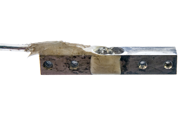
Put the four wires of the force gauge into thin silicone hose (ID about 2mm), apply some amount of sealant directly to the wires where they meet the gauge, about 30mm is enough, so that the wires adhere to the hose when you slide it all the way towards the force gauge. Apply sealant on top of the tube, closing any exposed parts of the gauge completely and everything together. Let it dry for a day after you are done.
Modifying Parts
All 3d-printable parts of the machine are designed in OpenSCAD and the original .scad files are included in the repository.
That means that you can modify the parts using OpenSCAD (or FreeCAD with OpenSCAD extension, I'm not here to judge).
You do not need to be familiar with any CAD software to fine tune the parts. Most of the dimensions you may wish to change such as inner and outer diameters of the hoses can be edited using graphical interface. The shape of each part is calculated from the parameters that have default value, but can be changed to fit your needs.
To make a 3d-printable .stl file in OpenSCAD, you need to open .scad file that contains the model, make "Parameters" section visible if it is hidden, choose the part you need from the drop-down list and change the parameters you want.
Depending on OpenSCAD version and your computer, the process of generating the part from parameters may take some time. Usually after you change some parameter, preview is automatically generated. Preview is a way to estimate if the changes that you make are the changes you want, it is faster, than generating the printable part but can contain some artifacts like missing or extra faces. Preview generation is also triggered by pressing F5.
To generate the actual part, press F6. It is usually slower than preview, but generates nice parts without artifacts. So-called nightly builds (or development snapshots) of OpenSCAD with Manifold library usage turned on are at the moment of wrighting way faster, although considered not stable. Or use any version you have, it's not that important for someone who is not an OpenSCAD-nerd like me.
To save the rendered part to an .stl file press F7.
Upper rail
- rod diameter outer diameter of the threaded rod.
- rods distance distance between rods of the upper rail.
Mounts parameters
- mount hole diameter of the screws that hold the valves, pumps, etc.
- part thickness minimal thickness of the load-bearing parts. About twice as thick as your comfortable wall thickness for not loaded parts.
- tightening gap a gap between two halves of the mount. Gives a room for tightening them together on a rail and for printing two halves as one part without having them stuck together.
- valve offset used to place the valves at certain distance from the plane of upper rail, for example to free some space for a decorative panel that covers parts of the machine.
- pump offset how far mounting points of the pump are lifted above the surface of the brackets
- mount hole distance distance between screws that hold the valve.
Filter attachment
- filter wall size of the negative space of the holding clip for the filter wall.
- offset v vertical offset, distance from mounting plane of the attachment to the top of the filter.
- offset h horizontal offset, distance from the axis of the attachment to the inner filter wall.
- hole diameter of the mounting diameter of the floating switch or the hose.
Advanced upper rail modification
There are brackets for mounting two types of pumps for filling the filter. If you have some special pump you can edit pump_shape function and add your own 2d shape.
Lower rail
- cut view just a visualization tool, only half of the part is rendered, so you can see the inner structure inside of OpenSCAD interface.
- override dbr force specific distance between rods (DBR) for the lower rail. Optimal DBR is calculated to minimize height of magnetic holder, however depending on magnet size and machine depth it may be impossible to fit the rail of optimal size inside the frame.
- rod diameter diameter of the threaded rod
- distance between rods if the previous parameter is set to true, sets the DBR for the lower rail. Make sure it is smaller, than the value returned by the frame.scad.
- tolerance affects several parts. It's distance between the walls of parts that are meant to go one inside another with some slack. Provides extra space for magnets, makes placing the vessels and the tank in their holders easier and allows helping tools for threading and tapping not to be stuck on the parts they help holding.
Interface
- light trap if the parameter is set, the hose interface is generated with extra bends inside, so the light can not pass through. Check for the developing tank interface, uncheck for all others.
- interface holes diameter of inner tube of the interface. Set this to inner diameter of the thread you want to cut in this part.
- seal length length of the threaded part.
- hor wall minimal thickness of a horizontal wall between inner tube and bottom in tank interface. Does not affect other vessel interfaces.
- offset used only for the tank interface, makes effect only if light trap is checked. Since developing tanks usually have some axis in the center it is impossible to mount the interface directly there. Offset is the distance between the center of the tank and where you drill the hole. If set correctly, the tank will be supported with its magnetic holder directly in the middle, although the interfacing hole is offset.
Printed thread and magnet
Those are the parameters of the 3d-printed threads used for mounting magnets. They do not affect the finer hose-mounting threads, which you need to cut with a tap and a die.
It is recommended to turn off layer expansion correction in the slicer and fine tune the tolerances here in the model itself. The reason is to have guaranteed minimal wall thickness. If the tolerance in the model is too small and you make it larger while slicing, the wall between the valley of the inner thread and the opposite wall of the part can become too thin for printing. To better understand the thickness of walls and tolerances between all of the parts, render the part called "test fit" with the "cut view" option on, it will provide a visual clue.
- thread pitch is the distance between two neighboring coils of the thread. It affects also how much horizontal space the thread takes, 3mm seems to be a good compromise between ease of print and material usage.
- thread expend horizontal distance between inner wall of outer thread and outer wall of inner thread in models, that guarantee their fit after printing. It should be at least twice the horizontal expansion of the print and smaller than thread pitch. Half of the thread pitch seems to be safely far from both limits.
- magnet diameter diameter of the magnet, no extra tolerance needed.
- magnet height height of the magnet, no extra tolerance needed.
- wall between magnets thickness of a horizontal magnet-separating wall. Keep in mind that there are two of those walls between magnets. The parameter affects maximal attraction force between magnets. This force should be just strong enough to hold an empty vessel when it is partially submerged into temperature stabilizing water bath and to keep it from floating. However the walls need to be strong enough to hold the magnets, so avoid weak magnets. 12x2mm neodymium magnets with 0.8mm wall seem to hold 500ml vessels and are two layers thick even when printing with 0.4mm layer height.
- wall minimal thickness of walls. Affects distance from thread valley to the nearest opposite wall, thickness of weight gauge mount on magnetic holder, position of rod mounting holes.
Hose adapter and hollow screw
- screw shape shape of the head. "Allen" option has only hexagonally-shaped inner hole for allen key and cylindrical head. "Hexagonal" and "Square" make polygon-shaped head in addition to hexagonally-shaped inner hole for allen key.
- adapter shape changes the shape of hose adapter and sleeve. Square takes more space which increases the height of interfaces, but is easier to grab. Round one is the most compact.
- hose inner diameter and hose outer diameter are self-explanatory.
- insert diameter and screw diameter are the diameters of hose adapter and hollow screw. Make it the outer diameter of the thread.
- adapter inner diameter and screw inner diameter are the diameters of inner channels inside hose adapter and hollow screw.
Magnetic holder
- rod mount true for mounting points for threaded rods, false for mounting onto weight gauge. The tank does not need rail mounts since it is mounted on a weight gauge.
- nut width space for tightening the holder on the rail, largest width of the nut (from edge to edge).
- cutout size of the slot in the cover that helps screwing
Weight gauge
- wg hole size diameter of the thread on the loaded side.
- wg hole distance center distance between threaded holes on the loaded side.
- wg ms hole size diameter of the thread on the clamped side.
- wg ms hole distance center distance between threaded holes on the clamped side.
- wg height and wg width are the dimensions of the force gauge.
Helper tools
- onside checked generates tapping tool for the side thread. Unchecked generates the tool for the top thread.
- leader length length of cylindrical part of the tap.
- tap length length of the threaded part of the tap.
- tap diameter diameter of a hole to fit the cutting part of the tap.
- leader diameter diameter of the cylindrical part of the tap.
- holding depth depth of the part inpression into the helping tool.
- die diameter outer diameter of threading die.
- die height height (thickness) of the die.
- handle length length of the bar that is used to turn the tool.
- handle thickness how thick is the turning bar.
- rounded handle the bar is round in cross section instead of square. Nicer to hold, harder to print.
Frame
OpenAutoLab is designed in such a way that it could be partially submerged into a heated water, which is held at a particular temperature. Rectangular plant container of sufficient size is a good option.
- rod diameter diameter of threaded rod used to build the frame. M8 seems reasonable, but you can try thinner or thicker rods.
- nut width is a largest width (from edge to edge) of the nut for the smaller screws that clamp the horizontal and vertical rods together (T-mounts).
- mount_hole hole for the clamping screw
- thin_wall minimal distance from the edge of the nut to the edge of the part
- thick_wall minimal thickness of the load-bearing parts
- tightening gap width of cut between halves of mounts, the more the tighter the halves can be pressed together.
- tolerance is here mostly for hole shrinkage compensation.
Enclosure
Careful with last three parameters, it is supposed, that mounting rectangle and viewing window share a center. If one is offset, make the slot bigger.
- tolerance tolerances for the board itself, for halves of the enclosure, for the buttons.
- pcb width with of the main board
- pcb height height of the main board
- pcb offset distance from the top of the board (component side) to the front side of the front panel. There should be enough clearance for both the components soldered on the board and for external ones: display and switches.
- pcb thickness thickness of the board material itself
- solder thickness distance from the bottom surface of the board to the furthest point on that side. Space occupied by soldered connections.
- mount hole diameter of the clamping screws and the mounting holes of the PCB
- wall wall thickness.
- buttons outer diameter of the buttons as seen from the outside.
- buttons inner outer diameter of inner structure holding those buttons. Twice the inner diameter is a good start.
- buttons height the height of the switches themselves. Distance between the component side of the board and the tip of the switch.
- buttons height height of the actual switch on the surface of the board
- switches diameter mounting diameter of the filter pump switch.
- screen pos coordinates of the center of the screen.
- screen mount vertical and horizontal distance between the mounting holes of the screen.
- screen mount holes diameter of the screws that hold the screen.
- screen rect the size of the protruding part of the screen, for which a rectangular slot should be cut on the front panel.
- battery h, battery w, battery d outer measurements of the battery holder so it can be enclosed
Advanced enclosure modification
Most of the parameters for this part are the positions of different components on the main board. If you modified the board layout, measure X and Y coordinates of the components (and holes) from the upper-left corner of the board and write them inside the code. Unfortunately such arrays of values cannot be set with GUI. However if you understand how to modify the board in such a way it does not fit the box anymore, you'll manage to modify the array also :).
- pcb_holes_pos array with coordinates of centers of the drilled holes on the PCB used for mounting it.
- buttons_pos array with coordinates of the centers of buttons.
- connectors array with coordinates and sizes of the holes on the sides of the enclosure for the wires to go through
- switches_pos array with coordinates of the centers of switches.
Agitation
Cap
- outer diameter is an outer diameter of cylindrical part of the tank where the lid is normally mounted. No correction for part thickness is required.
- outer depth how deep the lid is.
- extra lip width height of elevation inside the cap that provides extra tension which increases the friction between the tank and the cap. Does not need to be high, it's here mostly to make sure, that the contact point remains at the rim of the cap when the flaps are bent, not at the rim of the tank.
- extra lip height how high does the elevation go from the rim of the cap.
- parts thickness wall thickness of the part. Affects both strength and stiffness. If you want your part to be really strong, print it with thicker walls, you can compensate increased stiffness with other parameters.
- cutouts amount of cuts that allow the cap to stretch.
- cut width width of each cut. Doesn't need to be wide, just large enough to guarantee separation on printing.
- cut depth how far from the rim the cutouts go. When smaller, than outer depth the cut affects only the side of the cap. If the stiffness of the part needs to be further decreased, larger cut depth will make it to the flat part also.
Rod
- servo offset how far is the mounting plane of the servo from the rod.
- servo mount optimal diameter of the hole for servo axis. This parameter is better found experimentally by printing a gauge with the same printer settings that you plan to use for the rod itself. The diameter needs to be large enough so the axis can be forced in, but small enough so the axis cuts splines inside of it, keeping it from free rotation.
- rod diameter outer diameter of an agitating rod.
- distance to coupling distance from the plane going through the upper rim of the tank to the coupling inside the spiral. For the tanks that use protrusions inside the tube that holds spirals (or just a wall dividing this tube in half at some depth) to engage with the rod to agitate through rotation. Distance from this protrusion or wall to the cap.
- coupling length length of the slot, which moves the spirals. Can be over-sized without real consequences.
- coupling width width of the slot. Should be larger than protrusion/wall it engages with.
Mainboard PCB
Schematics and PCB layouts are stored in KiCAD 8 format.
Ordering the board online
Although the board is optimized for DIY production at home, you can order it online at well-known board-producing places. You can find pre-generated gerber files for PCB fabrication attached to the latest GitHub Release.
Making the board at home
Almost all of the traces are on the back side of the board, requiring only several jumper wires on the front side to be soldered to complete the circuit. There are no traces thinner than 0.5mm and no critically close elements. You can use toner transfer method or apply photoresist to produce the board out of one-sided clad. Look up online how to etch the board using those methods if you are unfamiliar with them.
The jumper wires are visualized as front copper layer in the Kicad file. I suggest not soldering the parts with lots of pins (such as Arduino board and motor driver) directly, but rather use header sockets. If you still want to solder Arduino directly, solder jumper wires first, because they go under it. Thick power-delivering wires in the area of darlington arrays are supposed to go over the ICs.
Doesn't matter if you don't have the drills thin enough to make the "vias" between layers, or the wires that can go through. Make the holes bigger and bend the jumper wires' ends in the direction of the trace rather then soldering them at one point.
Bill of materials
| No | Part | Quantity | Digikey-id |
|---|---|---|---|
| Arduino Nano | 1 | ||
| LM2596T-5.0 | 1 | LM2596T-5.0/NOPB-ND | |
| ULN2065B | 2 | 497-2349-5-ND | |
| Pololu DRV8874 | 1 | - | |
| Inductor 330uH | 1 | AIUR-06-331K-ND | |
| Schottky diode | 2 | 1655-SB140CT-ND | |
| Capacitor 330uF | 1 | 399-ESK337M016AE3AA-ND | |
| Capacitor 100uF | 1 | 399-6102-ND | |
| Tactile switch 6mm | 3 | 450-1650-ND | |
| Terminal block small | 8 | A98036-ND | |
| Terminal block large | 4 | 277-1667-ND | |
| Pin sockets | 2 | 2057-SMC-1-40-1-GT-ND | |
| Pin headers | 1 | 2057-PH1-07-UA-ND | |
| SPDT switch | 2 | EG2447-ND |
Arduino Code Dependencies
If you don't want to customize the software you can just use the Web Flashing Utility to flash the latest OpenAutoLab firmware to the main board.
These instructions are intended for people that want to modify the code.
Arduino IDE
The Arduino Legacy IDE is the easiest way to program the board. The official documenation contains guides on how to install the Arduino IDE v1.
Libraries
Install the libraries using the Arduino IDE library manager. Take a look at the official documentation for hints on how to install libraries.
You need the following libraries:
- The Arduino Servo library allows to control the servo motor.
- LiquidCrystal I2C by Frank de Brabander is the library that manages LCD output.
- The HX711 by Bogdan Necula library to manage load cell for measuring amount of liquid in tank.
General Information
This document is a user manual for an already built OpenAutoLab. If you want to build the machine, refer to the Build Instructions chapter.
If you are new to film development, there is some basic information in this manual, but please note that it is not the complete knowledge base. Please read the documentation on films and chemicals before using them.
OpenAutoLab is a machine designed to simplify the film developing process. It pumps necessary chemicals into developing tank, agitates the film properly for the correct amount of time, pumps the chemicals back, washes the film and does all of that without the help of the user. The user has to load the film into the tank, pour the chemicals into their vessels, connect to the source of clean water and drain for waste water, start the program, wait for the end of the program and dry the developed film. The machine can be used in tempertaure-controlled water bath to achieve good results in color processing or without one if temperature precision is not critical.
Disclaimer
I do not take any responsibility for any damage done by mishandling chemicals.
For most processes rubber gloves suffice to keep you safe, but please refer to documents provided with each chemical you use, some are more toxic than others. This document explains the details of using the machine itself, without much attention towards the handling of chemicals. Research online if you are unsure, use your brain and be safe.
Machine components and operation overview
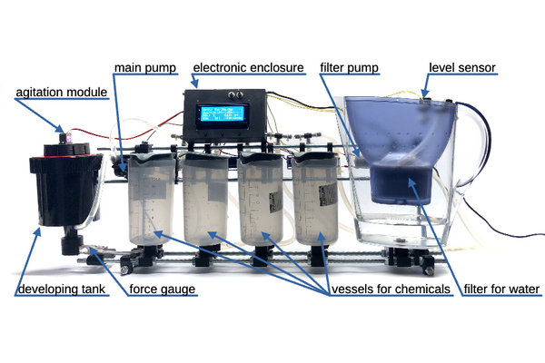
Developing tank is a special light-tight container, that allows the liquids to be pumped into and from it, while keeping the film in complete darkness. The film should be loaded into the tank also in darkness and is not allowed to be exposed to the light until the end of the development. The main pump moves liquid from the vessel into the tank through the valve, which is defined by the development process and is opened by the machine hardware electronically, and then pumps it back after defined amount of time.
The amount of the pumped liquid is controlled by the force gauge. The correct speed of the chemical reaction and its uniformity is achieved by agitation, i.e. rotation of film spiral inside of the tank with servo motor connected to agitating rod.
To avoid unwanted chemical reactions with minerals dissolved in tap water it is recommended to use distilled water instead, but in most cases tap water just passed through household filter don't leave significant impact on the picture quality, so the machine is build with such filter in mind. The water level on intake of the filter is kept high with the help of secondary pump powered through a float switch.
What does impact the final result are the water droplets left on film before drying: they can leave visible stains, which are residue of minerals that were dissolved in water. One possible solution to this is applying wetting agent on final wash, ideally dissolved in distilled water. Application of this wetting agent can be turned on in settings.
For some processes the chemicals anf film need to be stabilized at certain temperature. The machine was desidned with this in mind and its lower part is water-tight, so the user can submerge the vessels and the tank into water and keep it at desired temperature. For that a slow-cooker can be used (aka Sous Vide) or specialized film processing heater.
Praparation for film processing
Before processing any important film, especially if the machine was not in use for a long time, or after transportation, run an idle process without film, possibly with water instead of developing chemistry. For that I recommend entering service menu, filling all the vessels with clean water and running a cleaning cycle to make sure that all the valves are working and that everything is water-tight.
First of all you need to put the film in complete darkness onto the spiral inside of the developing tank. You can use the light-tight changing bag or the dark room. It needs to be completely dark, no red light is aceptable on this stage, even the tiniest amount of light getting into the room through the perimeter of the closed door can fog the film. If you can see the light, than the film can also "see" it.
Before doing it for real with the film you value, exercise putting the film onto the spiral first in daylight (use the already developed or ruined film strip), then exercise more with closed eyes, and then try the darkroom or changing bag, examining your work afterwards: the film loops should not touch each other and tank walls. Read the instructions of your developing tank or watch some videos on the internet on the topic if you need more information on loading.
Fill the vessels with chemicals. Study film development online a little if you are new. There are lots of different chemicals which are used for film developing, they should be stored and prepared differently, some of them are toxic, read the decumentation on your chemicals for exact instructions. The recommendation that I can give for beginners who did not buy any chemicals yet, is to start with black-and-white process in rodinal (aka r09) and fixing with literally any fixer in liquid form you can find (adofix, fomafix). Liquid concentrates are easy to measure and to mix with water, you just need a syringe and a couple of measuring cups.
Connect the intake of filter pump to water source: submerging the tube into 5l canister should do for developing one film. Turn on the clean water pump and make sure that some amount of water is filtered through: the machine is not going to wait if it needs prewash as the first step.
If you are developing color film or if you want to process black-and-white in higher than room temperature, use heated water bath. Submerge the machine into water-tight container filled with water and put temperature stabilized heater (slow cooker aka Sous Vide works perfectly for that purpose) set to wanted temperature into it.
Put the waste water output into another canister or put it directly into the sink. Make sure it does not run away during the pumping. After all preparation is done you can start the machine.
Initial screen
Agit: 30s/30s/5s
Wash:0x10m+3x5m+WA
B&W: 2    C41: 4
B&W   C41   Settings
On startup the machine shows overview of basic settings and gives the user a choice between developing processes and entering settings. First line shows the mode of agitation: duration of first agitation (directly after pumping each liquid into the tank), agitation period (time between consequent agitations) and agitation duration (length of each of those consequent agitations).
Second line shows the mode of film rinsing: number and duration of pre-washes, number of washes after development and if extra wash with wetting agent should be performed (if yes, letters WA appear on screen). Multiple pre-washes are necessary when developing cinema film with remjet: this remjet layer is first softened with hot stong basic solution and then can be washed away with water. Multiple rinses after development assures no fixer is left in film for archival storage. Wetting agent if needed should be poured into fourth vessel of the machine for both two- and three-stage processes.
Third line displays film count developed in current chemicals. It is important to keep track of it because of depletion: processing time for c41 is calculated from it and becomes longer as chemicals become weaker. For black and white this time recalculation is not implemented, it is expected that the user gives enters expected processing time before each development depending on film stock, developer type and dilution as well as depletion. The user can use one-shot developer like rodinal in which case there is no film count and the developer is pumped directly into waste water after use. More on that in settings.
The fourth line on this machine always depicts what pressing each of the buttons does. In this case you can start black-and-white or c41 developing process or enter global settings.
Black and white process
B&W developing
Film count: 2

Reset    +    Next >
If black-and-white process is chosen, and the developer is not one-shot (more on that in settings) you first land on film count page. Here you can reset the counter by pressing the first button or manually increment it by one with the second button. The incrementation is normally done automatically, so the manual option is added only if you have pressed reset by mistake and want to enter the correct value. The third button brings you to the next screen.
Developing time:
6:00

-      +      Next >
On the next screen you need to enter the development duration. The first button decraeses the time and the second one increases. Increments are not linear and increase as the value gets larger: small values have 5-seond steps, then 30 seconds, 5 minutes, 10 minutes, 30 minutes, 1 hour and 2 hours up to a maximal time of 42 hours. This is an obvious overkill for any standard processing, but can be useful in case you want to experimant with alternative processes (for example if using table salt as a fixer, some sources mention 24 hours as the correct fixing time)
Fixing time:
6:00

-      +      Next >
On the next screen you need to enter the duration of fixing. It works exactly like pre previous screen: the first button decraeses the time and the second one increases with the same exponential-like increment values. The third button starts the processing.
B&W develop    1/6
Developer   pump in

123.45       0:07
During pumping the chemicals into or from the tank the first line on the screen shows the name of the process, current substage index and the total number of substages (each rinse is counted as separate substage, so the user knows approximately how many processing stages are left). The second line shows the name of the substage and if the pump is working towards the tank or away from it. The last line shows the current value on the weight gauge and the total time passed from the processing start. Weight gauge shows negative numbers when the chemicals are pumped put (the weight of the tank decreases), and positive when the chemicals are pumped in. Nothing really changes if the tank is submerged into water of the heating bath: what is shown is the weight difference from the start, which buoyant force does not change. Important is not to change the water bath level during pumping and not to disturb the tank directly or by creating waves, because that can influence the measurements.
B&W develop    1/6
Developer   process
0:23 / 6:00
301.52       0:23
During the processing and agitation the screen shows the same information, but also additionally the time elapsed from the start of the substage and the duration of this substage on the third line. Not to be confuded with this substage timer is the process timer on the last line: it shows the time passed since the start of the film processing, not from the start of current stage in this multistaged process.
B&W develop    6/6
        Done
5:00 / 5:00
-312.64       28:30
When the processing is finished, the word "Done" appears on the second line of the screen and a sound signal brings users attention. You may now open the tank and get the film out for drying. Pressing any button will bring you to the initial screen.
C41 process
C41 developing
Film count: 2

Reset    +    Next >
If C41 process is chosen you land on film count page. Here you can reset the counter by pressing the first button or manually increment it by one with the second button. The incrementation is normally done automatically, so the manual option is added only if you have pressed reset by mistake and want to enter the correct value. The film count value is important as the chemicals become weaker with each development and the processing time is increased automatically. The third button starts the development.
B&W develop    1/10
Developer   process
0:23 / 3:15
301.52       0:23
The information on the screen as well as basic processing principles are the same as in black-and-white mode. The difference is only in number of chemicals involved and therefore number of substages.
Settings
Settings        1/10
Prewash duration
0:30
-      +      Next >
If on the main screen you chose to enter settings, the first page defines the duration of prewash. Prewash is important for bringing the film and the development tank to correct temperature before processing and for washing away antihalation layer. This duration is set up exactly the same way and to same values as processing durations. First and second buttons decrement and increment the value and the third one brings to the next screen.
Settings        2/10
Prewashes number:
1
-      +      Next >
Number of prewashing cycles at the beginning of processing. You can omit the step by setting the number to zero or you can use as many cycles as you wish up to 255.
Settings        3/10
Final washes duration:
5:00
-      +      Next >
Final wash is for getting rid of fixer traces trom the film, which is important for archival storage. This duration is set up exactly the same way and to same values as processing and prewash durations. First and second buttons decrement and increment the value and the third one brings to the next screen.
Settings        4/10
Final washes number:
3
-      +      Next >
Number of prewashing cycles in the end of processing. You set the number to as many cycles as you wish up to 255. Read the datasheet of your film to find the optimal number and duration of washes.
Settings        5/10
Apply wetting agent?
                 Yes
No     Yes    Next >
Wetting agent helps to reduce staining from non-distilled water. Third line shows the current value, first button sets to "No", second to "Yes" and the third updates the value and brings to the next page. If set to "Yes" than after the last rinse in water the machine will wash the film once more in the contents of the fourth vessel. As a wetting agent you may use commercial products like FotoFlo as well as DIY recipies such as droplet of soap in distilled water, glass cleaner for dishwashers and pure isopropil alcohol. Research online if you want to know more.
Settings        6/10
Initial agitation:
0:30
-      +      Next >
Duration of the first agitation performed directly after pumping the chemical into developing tank. This duration is set up exactly the same way and to same values as processing and wash durations. To set this value correctly as well as the next two, refer to film and developer datasheets.
Settings        7/10
Agitations period:
1:00
-      +      Next >
Time between two consequent agitations, to be more precice between the start of one agitation and the start of the next one.
Settings        8/10
Agitation duration:
0:05
-      +      Next >
For how long the servomotor performs each agitation (except for the first one which is usually longer).
Settings        9/10
Tank capacity:
300g
-      +      Next >
How much liquid should be pumped into the developing tank. Depends on the tank itself (some are wider than others) and type of film used (35mm film needs lower liquid level than 60mm medium format film). This value is also used for weight gauge calibration and for washing cycles (more on that topic in service menu.
Settings        10/10
Discard B&W dev?
                 Yes
No     Yes    Next >
Is the black-and-white developer one-shot, i.e. should it be discarded directly after use? If set to "Yes", the film counter does not show up and the used developer is pumped to waste after respective processing stage, not into its original vessel. Third line shows the current value, first button sets to "No", second to "Yes" and the third updates the value and brings to the next page.
Service menu
Some settings and functions are hidden in service menu, which can be accessed by pressing all 3 buttons simultaneously on startup. The motivation of keeping those separate is that they can mess up internal calibration or chemicals that are in the machine's vessels if the wrong button is pressed. If during startup all 3 buttons are pressed, you will see "Service menu" on the screen. Release the buttons immediately and you will see weight gauge calibration page. To calibrate the weight gauge you need to set it to zero by pressing the first button, then pour amount of liquid written on screen into developing tank (this amount can be changed in regular settings) and press the second button. If everything is done right the screen should show correct weight on the third line. To store new calibration values press the third button.
Next pages contain debug and test procedures. At the moment of release there is a program that fills all the vessels (and if needed also the tank) with water and a program that empties the vessels (if needed), fills them up with water and emties again. Use the first one and turn off the machine for some time to test that all interfaces are water tight. Use the second one as a cleaning cycle. I run the first program to fill the vessels and tank, add some basic cleaning solution in each of them and run the second program to rinse. Those programs are work in progress.
Web Flashing Utility
Use this page to upgrade the Firmware on the OpenAutoLab Main Board to the latest release or dev build from the OpenAutoLab GitHub Repo.
How-To
-
In the
Downloadbox, keep the pre-selectedReleaseschannel. -
Press the
Fetch Versionsbutton. -
If in doubt, use the pre-selected latest
Versionthat appeared. -
Press the
Download Firmwarebutton. This will start a download in your browser. -
In the
Uploadbox, press theChoose Filebutton. -
Select the file you just downloaded in the previous steps.
-
Press the
Upload Firmwarebutton. This will start the flashing process. -
Wait until you either see a success message or an error indication in the status log.
Troubleshooting
Make sure you use a WebSerial compatible browser like Chromium, Chrome or Edge.
Connect the Arduino Nano on the OpenAutoLab mainboard to your PC using a USB cable.
This should work on Linux, Mac OS X and Windows >= 10.
The Releases downloads should always work.
For the development Builds downloads you need to be logged-in to GitHub and they can not be too far in the past.